The map can be used to help align TV & radio aerials and satellite dishes, and tuning information for TV & radio transmitters.
Choose the required service button (above) to begin: 
Satellite
The list of satellites is based on the Lyngsat listing for Ku band satellites (C band only satellites not included).
Last update: 2nd June 2012.
The first step is to place the purple "home" marker  onto the map.
Enter a postcode in the "Address or postcode:" box above the map and press "Submit" (or alternatively click on the map).
The map will centre and zoom in to the chosen point.
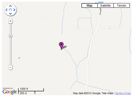
The purple marker can now be "dragged" to the desired location (place cursor on purple marker, left click & hold, then move the mouse to drag the purple marker as required).
Zoom the map in or out as necessary using the mouse wheel (or the slider on the left hand side of the map) to view the required location.
For best accuracy, set the map viewing option to "Satellite", using the  controls at the top right of the map, and zoom in as necessary (mouse wheel) to pinpoint the exact location.
Underneath the map is the data section:
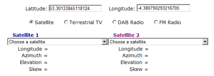
The Latitude and Longitude values correspond to the tip of the purple marker. These values are necessary for a motorised satellite dish setup, so the receiver can calculate the correct motor movement. Longitude values are shown with negative values for "West" and positive values for "East".
Two drop down lists (Satellite 1 and Satellite 2) are provided (with identical lists of satellites in each). Selecting a satellite places a line onto the map showing the azimuth alignment from the purple marker to the selected satellite.

Once a satellite is selected, corresponding data for azimuth, elevation and skew appear in the data section.
In the drop-down lists, the satellite for Freesat / Sky TV (at 28°E) is shown with a yellow highlight (if your browser supports it) to make it easier to find.
| Azimuth: | The horizontal angle (degrees clockwise from true North) for the selected satellite. |
| Elevation: | The vertical angle (degrees upwards from horizontal) for the selected satellite. |
| Skew: | The apparent angular tilt of the earth's equatorial plane at the selected satellite. |
N.B. Most satellites typically have their polarisation aligned with the equatorial plane.
However, some don't (e.g. 28E, 19E, 13E), requiring the LNB on the dish to be adjusted accordingly.
Terrestrial TV
This section has data for all UK terrestrial transmitters listed by Ofcom (other than self-help relays).
Details for Ireland (Saorview) will be added at a later date.
The page features are detailed below:
| 1. |
Above the Google Map is a text entry box for an address or a UK postcode: 
Entering a postcode and pressing "Submit" centres the map and zooms in to the postcode entered.
A purple marker is placed on the map at this location.
Users can "drag" (click & hold) this purple marker to their precise location. The map retains the standard viewing options at the top right, so aerial locations can be pinpointed (e.g. on a chimney stack).
Data entered is not collected. Users may click on the map to set their approximate location if preferred.
|
| 2. | Map section:
The Google map can be "dragged" (click and hold, but not on a marker) and zoomed (mouse wheel).
Clicking on the map places the draggable purple marker onto the selected location, and automatically centres and zooms in on the map.
Clicking on the map subsequently at a different location will move the purple marker to that new location.
|
| 3. | Data section:
Below the map are readouts for the latitude and longitude corresponding to the tip of the purple marker.
Below the latitude / longitude data are two drop down boxes containing a list of transmitters and a list of relays.
The list of relays shown changes to correspond to the particular transmitter selected (as per Ofcom data).
Range & bearing values are shown if the purple marker has been placed on the map, and a transmitter or relay is selected.
|
The two drop down boxes ("Transmitter" & "Relay") show the "main" (mostly high power & 6 MUX) transmitters, and the "fill-in" (mostly low power & 3 MUX) relays.
The relay list changes in accordance with the particular transmitter selected.
The transmitter list in the drop down box is in alphabetical order. Most of these transmitters carried the digital services prior to switchover.
The relay list is also shown in alphabetical order. Most of these relays did not have any digital service prior to switchover.
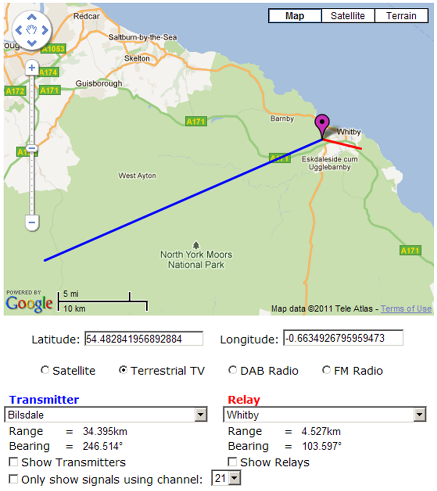
If a purple "home" marker is shown on the map, selecting a transmitter from the "Transmitter" list will create a blue geodesic line on the map, from the tip of the purple marker to the selected transmitter mast. Corresponding data for the range (in kilometres) and bearing (degrees clockwise horizontally from true North) is show underneath.
Selecting a relay from the "Relay" list will create a red geodesic line on the map with corresponding data underneath.
Since the names of transmitters or relays may not be known, tick boxes are provided (underneath the range and bearing data) to add markers to the map.
Check the "Show Transmitters" tick box (may take a second or two to load the data) to put coloured markers onto the map to identify all of the "main" transmitters in the UK (zoom out to see them).
The marker size is related to the number of MUXs present on a transmitter. Most of the "main" transmitters have 6 MUXs, represented with a large marker.
The few transmitters with 3 MUXs are show with a small marker.
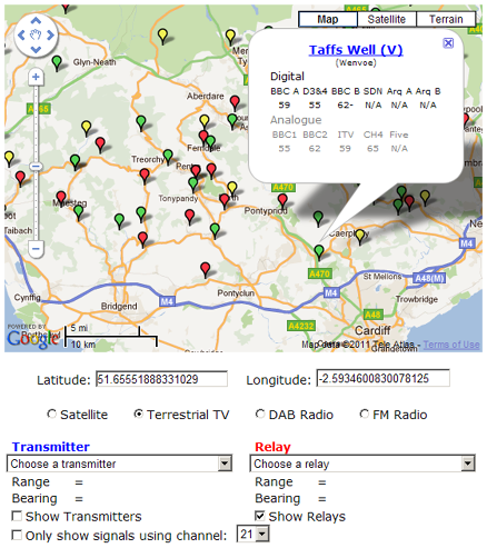
Clicking on one of these coloured markers opens an information window showing the transmitter name and UHF channel numbers for both digital and analogue TV, and switchover dates for pre-DSO transmitters:
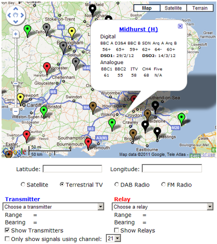
Where transmitters have already switched, analogue services are not available and the "Analogue" data is greyed out (but is still readable to show the UHF channels previously used - useful when the aerial group has changed).
The DSO1 and DSO2 dates are shown for transmitters pre-switchover. Post switchover, these disappear.
The marker colours for each transmitter correspond to the aerial group required for reception currently. N.B. some transmitters revert from "wideband aerial" to "grouped aerial" after switchover.
The marker colours follow the convention for TV aerials:
| | Colour | Group | UHF Channel range |
| | Red | A | 21 - 37 |
| | Yellow | B | 35 - 53 |
| | Green | B | 48 - 68 |
| | Brown | B | 35 - 68 |
| | Grey | B | 21 - 48 |
| | Black | B | 21 - 68 |
Checking the "Show Relays" tick box (may take a while - browser dependent & a lot of data) places coloured markers onto the map to identify each relay.
Most of the relays provide a 3 MUX service, represented with a small marker.
The relays that provide a 6 MUX service are represented with a large marker.
Relay markers can be clicked on to open up an information window:
The information window shows the name of the Relay, with the name of the parent transmitter underneath in brackets. This enables the correct transmitter to be selected from the drop down list to give the corresponding relay list (where the required relay can easily be found). Relay marker colours represent the conventional aerial groups shown previously.
Where the exact date for digital switchover hasn't been announced, the date is given as the year alone. These dates will be shown properly when the information becomes available. Post switchover, the DSO dates are not shown, and the (old) analogue channels become "greyed out".
The relay markers "disappear" when the map is zoomed out. This makes the map easier to navigate; otherwise dragging the map would become excessively slow. Zooming in again makes the relay markers "reappear".
Under the "Show Transmitters" & "Show Relays" tick boxes, is another tick box:  with an adjacent drop down list of all the UHF channels (21 to 68).
Checking the tick box will remove the markers for all transmitters that don't have either analogue or digital signals on the selected UHF channel, leaving just those that do:
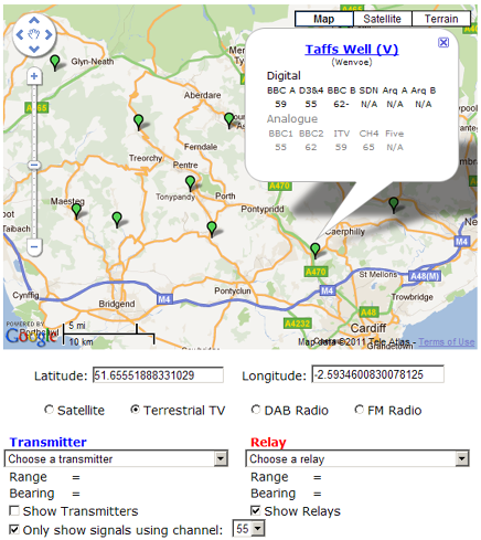
In the example above, all the red & yellow relay markers have disappeared, along with some of the green markers. Only the (green) markers remaining have one MUX on UHF channel 55 (or one analogue channel for pre-switchover relays).
The transmitter name inside the information window is "clickable" - clicking on it will bring up the radiation pattern for that transmitter (or relay). Click the X to close the info window and leave the pattern overlay on the map.
N.B. Most "main" transmitters do not have published patterns - a dotted circle is shown for these transmitters. The centre of the circle is located at the transmitter mast, and the radius of the circle is approximately representative of the range over which a normal domestic aerial (unamplified) might receive a signal, if the radiation pattern was uniform around the transmitter (many aren't).
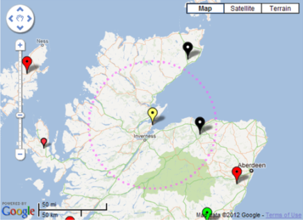
The area indicated by the dotted circle (or actual pattern if available) does not represent coverage, since that is significantly affected by terrain (e.g. hills in the way).
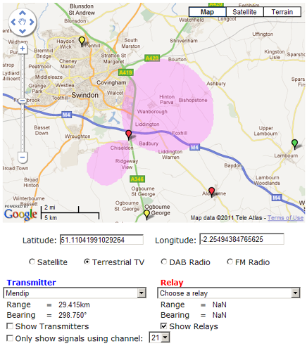
Many of the relays do have published patterns - a semi-transparent "patch" is overlaid on the map indicating the direction of the signal and likely range for a normal aerial. Again, this is not representative of signal coverage, since terrain is not accounted for.
The pattern indicates the direction that the signal is emitted (and perhaps more significantly the direction(s) that it isn't).
DAB Radio
The DAB transmitter information used here is based on Ofcom's "radio tech parameters", which enables all the DAB transmitters in the UK to be shown on the Google Map above.
Additional information for each DAB Ensemble, Frequency Block and radiation pattern (where available) is also included.
The DAB map features are detailed below:
| 1. |
Above the Google Map is a text entry box for an address or a UK postcode:
Entering a postcode and pressing "Submit" centres the map and zooms in to the postcode entered.
A purple marker is placed on the map at this location.
Users can drag this purple marker to their precise location. The map retains the standard viewing options at the top right, so aerial locations can be pinpointed (e.g. on a chimney stack).
Data entered is not collected. Users may click on the map to set their approximate location if preferred.
|
| 2. | Map section:
The Google map can be "dragged" (click and hold on the Google Map and then move as required) and zoomed (mouse wheel).
Clicking on the map places the draggable purple marker onto the selected location, and automatically centres and zooms in on the map.
Clicking on the map subsequently at a different location will move the purple marker to that new location.
|
| 3. | Data section:
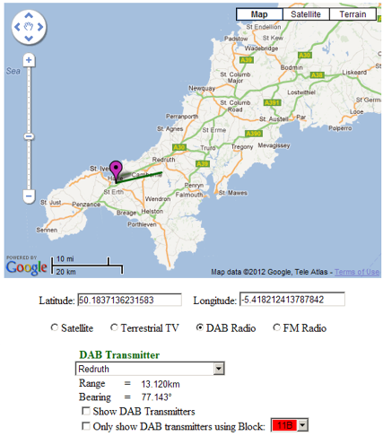
Below the map are readouts for the latitude and longitude corresponding to the tip of the purple marker.
Below the latitude / longitude data is a drop down box containing a list of DAB transmitters.
Range & bearing values are shown if the purple marker has been placed on the map, and a DAB transmitter has been selected.
|
The drop down box ("DAB Transmitter") show the DAB transmitters operating in the UK, in alphabetical order.
If a purple "home" marker is shown on the map, selecting a transmitter from the "DAB Transmitter" list will create a green geodesic line on the map, from the tip of the purple marker to the selected DAB transmitter mast. Corresponding data for the range (in kilometres) and bearing (degrees clockwise horizontally from true North) is displayed underneath the DAB transmitter drop down box.
Since DAB transmitter names may not be familiar, a tick box:- "Show DAB Transmitters" is available (below the Range and Bearing data).
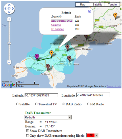
Check the "Show DAB Transmitters" box (may take a few seconds to load the data) to place coloured markers onto the Google Map identifying the locations of all the DAB transmitters in the UK (zoom out to see them all).

The marker colour indicates how many Ensembles are present on a particular DAB transmitter :-
| Marker | Colour | Number of Ensembles |
 | Brown | 1 |
 | Red | 2 |
 | Orange | 3 |
 | Yellow | 4 |
 | Green | 5 |
Clicking on one of the DAB transmitter markers opens up an information window showing the name of the DAB transmitter and the Ensemble(s) being transmitted (left column). The frequency block for each Ensemble is shown in the right hand column.

Because DAB uses a single frequency network, all BBC National DAB Ensembles appear on Block 12B. Similarly, most of the D1 National Ensembles appear on Block 11D (except in Scotland, where 11D is used for the Central Scotland Ensemble and D1 National is on Block 12A).
Each Ensemble name in the information window is "clickable", producing a semi-transparent image on the Google Map to indicate the horizontal radiation pattern from that transmitter, for the particular Ensemble selected.
N.B. Different Ensembles can have different patterns and / or different E.R.P. (effective radiated power).
The radiation patterns (if available) are coloured to match the particular frequency Block being used:
| Ensemble | Colour |
| 10C | Dark Red |
| 11B | Red |
| 11C | Orange |
| 11D | Yellow |
| 12A | Green |
| 12B | Light Blue |
| 12C | Blue |
| 12D | Dark Blue |
The radiation patterns for each Ensemble on a single transmitter can be overlaid on the Google Map :-
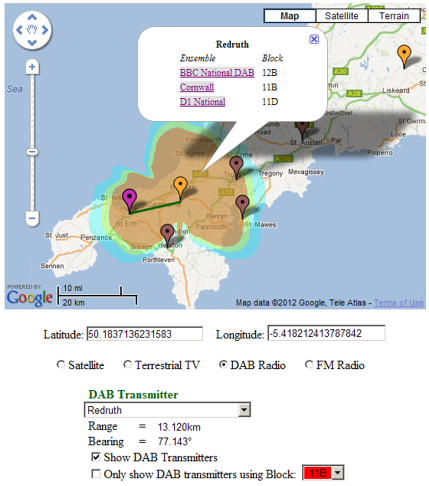
To make the radiation patterns easier to see, the information window can be closed by clicking the X (top right), leaving the radiation pattern(s) visible on the map.
Clicking on any DAB transmitter marker will remove any radiation pattern(s) shown on the map.
The radiation patterns have a size (radius) related to the transmitter E.R.P.
N.B.The radiation patterns do not indicate coverage, which would take the effect of terrain (e.g. hills) into account between the transmitter and the receiver.
The outer edge of the pattern is intended to give an idea of the limit of reception for a DAB radio inside a house, not connected to an external DAB aerial.
Where the radiation pattern is not available for a particular Ensemble, a grey dotted circle is placed onto the map, indicating the maximum extent of the pattern (data not available). The actual radiation pattern could have any shape inside this dotted circle.
The Stockland Hill transmitter has three Ensembles, but only one published radiation pattern, so viewing all Ensemble patterns gives the following :-
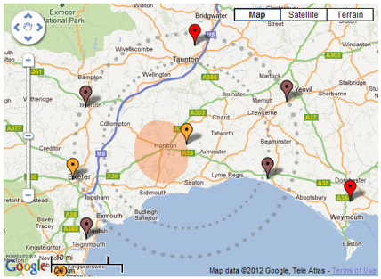
For Stockland Hill, the BBC National DAB Ensemble gives the larger dotted circle, with the D1 National Ensemble shown by the smaller dotted circle. The orange pattern inside the two dotted circles shows the South East Devon Ensemble using Block 11C.
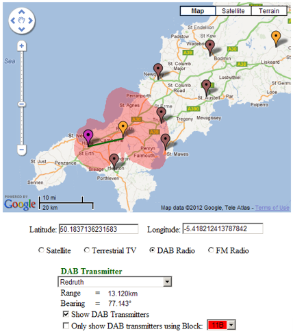
Below the "Show DAB Transmitters" tick box is a second tick box :- "Only show DAB transmitters using Block:" with an adjacent drop down box (11B, 11C, 11D, 12A, 12B, 12C, 12D)
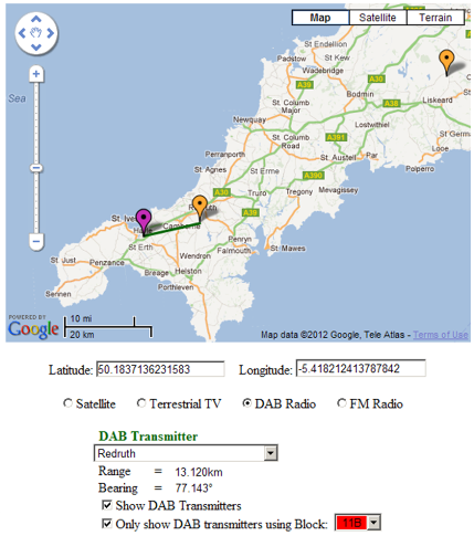
Selecting a specific frequency Block (e.g. 11B) filters the markers on the Google Map to show only those with an Ensemble using the Block selected.
In the example above, only the Redruth and Caradon Hill transmitters carry the Cornwall Ensemble on Block 11B, even though there are other DAB transmitter in this part of the country.
FM Radio data has yet to be added to the map - work in progress!