

RF Distribution
The digital switchover presents a bit of a nightmare for hotel owners and (on a much smaller scale) the same problem applies at home - should each individual TV set have its own digibox, and what alternative ways of routing TV signals are available?
Starting with the simplest possible configuration:
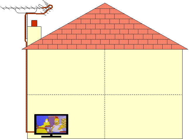
The TV aerial feeds down to one TV and provides analogue (if the signals are still there) and digital signals (if they are available).
There is no distribution here, any other TV set would be working independently (e.g. from a set-top aerial).
By adding a "loft box" the TV aerial signal can be distributed to a number of different rooms, providing both the analogue and digital signals at each TV outlet:
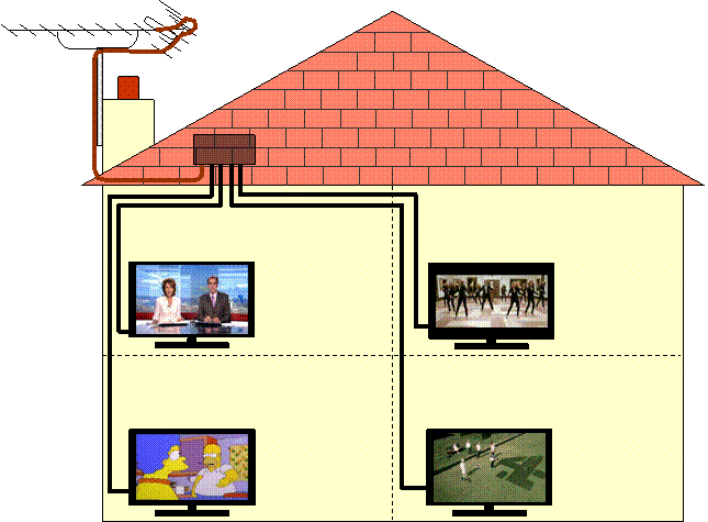
Provided each TV set has its own tuner / digibox, then all TVs are capable of viewing independent channels. This is a simple aerial distribution configuration.
A digibox for every TV set works fine if there is an aerial distribution system in place. Relying on a set-top aerial for Freeview may give picture and sound interruptions due to insufficient signal or margin.
By routing the TV aerial down to the lounge initially, it is possible to "add" another "channel", which could come from e.g. a VCR, a Freeview box (with modulator), or from a Satellite receiver (with modulator):
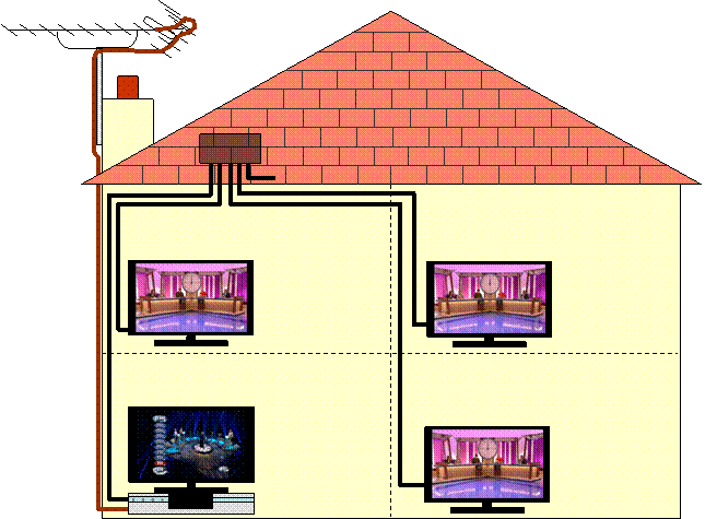
The output from the UHF modulator has all the original TV signals from the aerial plus one additional analogue channel, which is fed back up to the loft box for distribution around the other rooms / TV sets. One Freeview box in the lounge can then be viewed on all the other TVs, but they are restricted to watching the same Freeview channel that has been selected in the lounge (unless they have their own dedicated Freeview box).
The channel number used for the additional "channel" can usually be adjusted, but needs to be carefully chosen to avoid interference with the other analogue channels.
By feeding the TV aerial direct to the lounge initially, one output from the loft box has now become spare (or available for connection to a fifth room).
Almost all VCRs include a UHF modulator where all the TV signals are "looped through" from the aerial input, and the video signal from the VCR is provided as an additional analogue TV channel. VCRs are often pre-set to channel 36 for their UHF output (which can be changed if necessary to avoid interference). A VCR can be used to provide a UHF output from a Freeview box by connecting a SCART cable from the Freeview box to the VCR and then setting the VCR to the appropriate AV input for the SCART connection. This will modulate the Freeview channel as an analogue signal which can be viewed on any analogue TV (tuned to the VCR's modulator channel number).
RF Modulators for domestic use have several inherent limitations:
| a) | The output signal is analogue. |
|---|---|
| This requires the remote TV set to have an analogue tuner to be able to watch the modulator's output channel. Modulators with a digital output are available at huge cost, so aren't yet available for domestic use. | |
| b) | The output signal occupies two 8MHz channels (DSB modulator). |
| This contributes to the difficulty in finding a suitable channel number that avoids interference. | |
| c) | The sound is in mono. |
| Nicam stereo modulators are available for large scale distribution systems (expensive), but domestic ones are mono. |
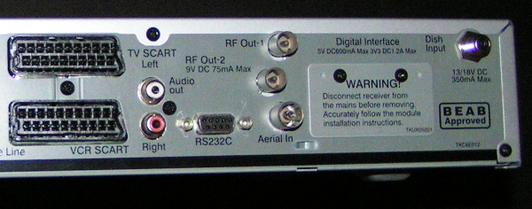
Modulators can be bought quite cheaply as a separate item to provide a UHF output for e.g. a digibox that does not incorporate its own modulator. The photo below shows a Mercury unit:
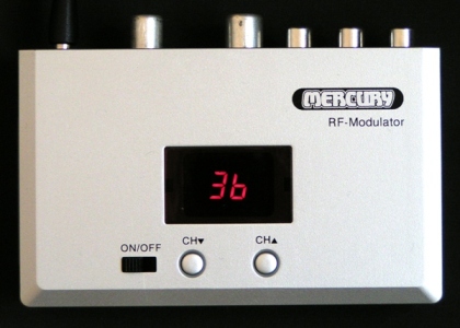
This device has a SCART "through" connection (SCART input to SCART output), but it has only the composite video and stereo sound connections linked (i.e. it does not provide RGB "through" as supplied). The SCART IN / OUT sockets are handy if only one SCART socket is available on the digibox (N.B. two SCART leads are still required for connecting). The modulator output channel is displayed on the front of the unit and can be easily changed using the buttons.
Although both left and right audio connections are provided at the SCART sockets, the L & R signals are buffered and summed together inside the unit, giving a single mono audio input to (and output from) the UHF modulator.
For hotels, having a digibox in every room represents a significant expense, but is cheaper than replacing every TV set with a digital ready one. The disadvantage is that the digibox is vulnerable to being "fiddled" with, or possibly stolen (not such a concern now that they are low cost).
An alternative option for hotels is to use a Multibox system that receives six digital channels, converts them to analogue signals (using six modulators) and then recombines them with the original aerial system.
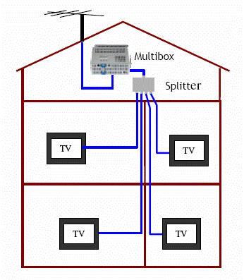
This provides at each TV outlet six "analogue" Freeview channels (any six channels can be selected, but are effectively "preset") as well as the "loop through" TV aerial signals. The multibox modulators are Nicam stereo capable, so the analogue channels do have stereo sound. This enables six Freeview channels to be viewed on existing analogue TVs, but the analogue channel setup requires a deal of care to avoid interference. Adding a digibox at any of the TV outlets enables all the digital MUXs to be viewed as normal.
Particular care is required with the UHF channel planning when using a Multibox (or other system utilising an array of Freeview receivers), since the UHF outputs are analogue signals and require careful selection of suitable channel numbers where no other UHF channels are located. This can require the use of filters to "clean" a suitable section of the UHF spectrum, allowing these channels to be used without risk of interference. The same criteria for selecting channels that avoid 5 and 9 separations also applies.
Coax cable distribution is often used for domestic installations with a Sky satellite receiver - the second RF output is connected by a coax cable to a remote TV which will display the same programme as being received by the Sky satellite box. The Sky receiver incorporates a modulator, and provides UHF aerial connector outputs on the back of the unit. If the RF modulator output signal is connected to a suitable distribution amplifier, it can be fed to multiple TV outlets. As before, all outlets receive the same programme. Infrared sensors are available that allow control of the Sky box (or other programme source) from the remote TV, back down the coax cable (utilising the RF Out-2 9V DC power supply to operate).
Coax cable distribution systems for UHF signals are well established, but TV picture information can also be sent as "wireless" RF signals or as AV signals (where the video and audio components are carried independently using e.g. SCART leads or Ethernet cables).
Domestic Distribution Unit
For houses that require both satellite and terrestrial services, a domestic distribution unit (DDU) can provide a combination of signals to various locations:
The DDU provides four inputs from a satellite dish quad LNB, which are fed through the unit to four satellite outputs with UHF signals from a terrestrial aerial, CCTV, DAB aerial and FM aerial added in. The separation of these signals is achieved at the wall plate (by filters), giving separate satellite and terrestrial signals:
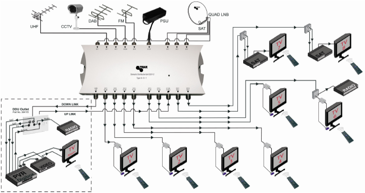
The remaining six outputs from the DDU are the combined non-satellite inputs (UHF, CCTV, DAB and FM), which are again separated at the wall plate. The whole system provides terrestrial signals to six rooms, two rooms with a single satellite feed and terrestrial signals, and one further room (e.g. lounge) with two satellite signals (for e.g. Sky+) as well at the terrestrial signals.
Satellite Multiswitch
Where an independent satellite signal is required in every room, two options are available:
a) Use an octo LNB, which can provide single feeds to eight rooms or dual feeds (e.g. Sky+) to four rooms.
b) Use a multiswitch, which can provide as many feeds as it has outputs.
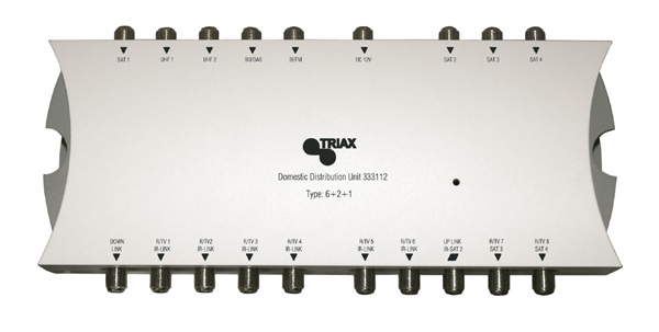
A multiswitch looks like this:
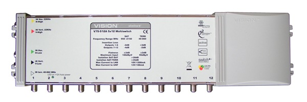
The multiswich has five inputs on the left-hand side, four from a satellite dish LNB and one terrestrial input (which can be a combined UHF, DAB and FM) signal.
The multiswitch shown above has 12 outputs, all of which can independently access the required satellite signal since the multiswitch acts as a buffered matrix switching unit. This unit can provide a single satellite feed to 12 rooms, or dual feed (e.g. Sky+) to six rooms. The UHF and satellite signals are diplexed inside the multiswitch, requiring appropriate filtered wall plates to separate the satellite and UHF/VHF signals.
Multiswitches are availble with even more outputs if required, and splitter units can be used to distribute the satellite LNB feeds to more than one multiswitch.
Wireless Distribution
"AV senders" use frequencies similar to WiFi and microwave ovens (2.4GHz) to transmit one channel / programme of analogue video and sound over a short range. These devices are useful where installation of other wiring is difficult, though they don't work well through thick stone walls.
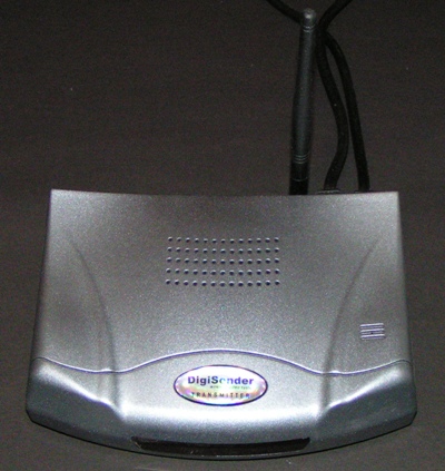
Some units also allow the remote control to operate back through the radio link (at a much lower frequency), to allow channel changes etc. Picture quality can be affected by the process, though is usually at least "fair", and these devices can be affected by e.g. people moving around close to the transmitter or receiver. The input is usually via an in-line SCART connector, and the output (via a similar looking unit) is also on a SCART connector. Don't be fooled by names such as "Digisender"; these units transmit the sound and video (composite) as analogue signals - the only digital content is the remote control feedback link. In this respect, these units differ significantly from WiFi.
Cabled Distribution
Ethernet TV distribution systems use conventional CAT5 cable (as used in offices for computer networks). CAT5 cables have 4 twisted pairs of wires which can be used up to 100MHz and 100Mb/s. Higher specification CAT5e is still rated at 100MHz but will allow data rates of up to 1000Mb/s. CAT6 cable is rated at 250MHz and 1000Mb/s and has a lower insertion loss. The frequency limitation of twisted wire pairs (compared with coax cable) makes Ethernet suitable for carrying video frequencies or data streams, but prevents them from being used for RF signal distribution.
There are two different types of system that utilise CAT5e / CAT6 cables:
| Analogue distribution - using the twisted pairs like a SCART lead. |
| Digital distribution - several MUXs can be carried on one twisted pair. |
Ethernet analogue distribution carries composite video and stereo sound on three of the twisted pairs of wires. This system (AVi Lynx) is available from Global Communications (UK) Ltd:-
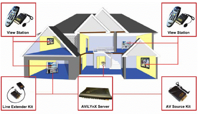
Up to 8 sources (or programmes) can be supplied using this technology.
Remote IR control is supported with this system.
N.B. Because the system is analogue, it is not compatible with an existing CAT5 installation already being used for a computer network.
Ethernet distribution with digital signals is known as IPTV (internet protocol television). This technology is compatible with existing computer networks.
The following diagram helps to explain the system (courtesy of Netvue - a company specialising in the supply of IPTV systems for business use):-
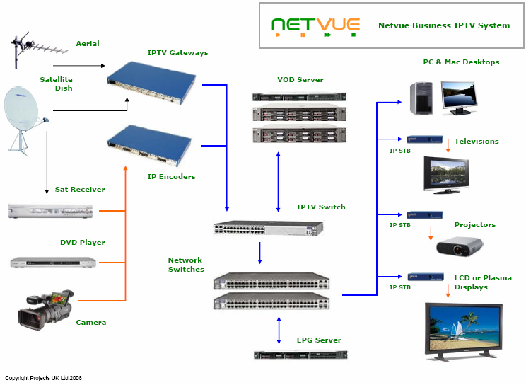
On the left hand side of the diagram are various video signal sources. The TV aerial and satellite dish provide digital MUX inputs. The satellite dish, DVD player and camcorder are shown providing analogue inputs.
The digital MUX inputs are fed to an IPTV gateway that receives the MUXs required and extracts each programme into its own MPEG data stream.
The analogue video inputs are fed to an IP encoder that transforms each analogue signal into an MPEG data stream.
Once the required signals are available as MPEG streams, an internet protocol "wrapper" is added and the digital video signals are then in a format that can be handled by conventional Ethernet switches.
The centre section of the IPTV system above shows the network switches and associated servers. The video on demand (VOD) server provides the functionality of a hard drive recorder to each user / destination / room, giving "playback on demand".
Also shown is an electronic programme guide (EPG) server, which provides information for TV channels on the network and can also be customised to add "network only" channel information.
This flexibility is useful for e.g. hotels that require their own "Hotel TV" channel.
The right hand side of the diagram above shows various options for viewing the video content / programmes on the network. Computers require media player software to watch programmes. Standard TVs would require an IP "set top box" to convert the data stream into an appropriate picture format, which can including high definition (HD) streams (via an HDMI interface).
Network efficiency is maintained by providing the data stream only to the specific destination that requests it (using multicast protocols). Each channel stream is placed on the network only once, with replication (for other destinations requesting the same stream) being handled by the network switches.
A big advantage of IPTV distributed over ethernet is the local network speed and capacity, which is typically much greater than is available on the internet at present. Additionally, the internet is not multicast capable - large numbers of high resolution TV channels would create major bandwidth problems for internet service providers.
IPTV technology looks set to be developed much further and the concept of distributing complete MUXs around the house maintaining their digital format could well become the preferred technology for the future. This method of processing is at the heart of cable TV systems, where whole MUXs can be transferred via a broadband internet connection overnight and stored on the cable digibox's hard drive for watching the following day. A standard CAT5e network used like this is still able to operate as a conventional data link between computers and a server - the digital MUX content is simply more traffic over the network. The system in principle isn't limited to a finite number of programmes, but each MUX required needs its own tuner if broadcast signals are being used to supply the programmes.