

Freeview Reception
The advice from Digital UK is to check your aerial by using the test page on Ceefax (Page 284), shown below:
This gives an idea of the reception "quality" by looking at the analogue channel (carrying the Ceefax data). Experience, however, shows that this doesn't necessarily represent the situation on the digital channels, and other factors are important which are beyond the capability of a simple Ceefax check.
One of the problems with digital reception is that it really is "digital": the picture either seems perfect or it can be completely unwatchable (or unavailable).
Interference
A number of factors can contribute to poor digital reception:
Digital signal is too weak.
Digital signal is too strong.
Co-channel interference (from another transmitter).
Adjacent channel interference (from analogue TV channels).
Digibox (auto) tuned onto the wrong transmitter.
The key requirement for good digital reception is to have a good signal to noise ratio. To achieve a high (good) ratio requires sufficient signal (or carrier as it referred to for digital), and a low level of noise.
Signal is the power corresponding to the required TV channel or MUX received by the aerial & fed down the coax cable to the TV set.
Noise is the power received by the aerial & coax that wasn't transmitted as part of the required TV channel (or MUX for digital reception).
Sometimes a specific location can prove to be "difficult" for digital reception - the following examples help to explain some of the issues associated with "signal" and "noise", and when the Ceefax checker is of little benefit.
Weak Digital Signal
Lots of things can contribute to a weak digital signal:
No digital transmission available.
This can be the case where reception is provided from a relay transmitter which won't provide any digital signal until the current analogue signals are switched off. See the Local Transmitters page for more information.
Aerial in poor condition
The aerial needs to be capable of receiving sufficient signal for the digital receiver. Aerials (especially near the seaside) can corrode badly on the terminals for the coax cable whilst otherwise appearing in reasonable condition.
The aerial must also be pointing in the right direction (i.e. at the transmitter), and with the correct orientation (polarisation).
The aerial also needs to correspond to the transmitter frequency - many aerials are now "wideband" aerials which give some response across the whole frequency range, but grouped aerials (optimised for a specific part of the range) are still common and can be important for good reception. See the Aerials & Coax page for further details.
Coax cable loss
The vast majority of "old" coax cable uses "air-spaced" insulation between the inner core and the outer screening braid, achieved with a polythene spacer, and has a cross-section similar to this:
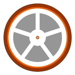
The five air pockets (grey) around the centre core help to give the coax cable the correct impedance (75 ohms) with a low loss. This is fine whist the pockets are filled with air, but if any water gets into the cable (possibly from damage or from an exposed connector box on an aerial), then the cable loss becomes very high.
Nails through the coax (from poor installation) can be another cause of high cable loss.
Strong Digital Signal
Digital signals can be too strong in some locations, and this can give just as much trouble as a weak digital signal.
Some makes of digital TV (Panasonic in particular) seem to have more sensitive digital tuners. This is useful when the digital signal strength is low, but will reach overload more quickly when presented with a strong signal.
The symptoms of digital signal overload can appear identical to those of a weak signal - the picture shows pixellation and the sound breaks up. This condition is easily resolved by adding an attenuator in the signal path to reduce the input to the correct level.
Digital signal overload isn't just restricted to the aerial input of the TV; the input to a distribution amplifier is just as susceptible. This particular problem became noticable after the antenna changes on the Beacon Hill transmitter which increased the analogue signal power in some locations (see the Local Transmitters page for the saga of the transmitter changes).
The analogue signal strength increased - but how did this affect the digital reception?
A distribution amplifier works on both analogue and digital signals (even if you only want digital TV, the analogue signals are still present until April). The increase in the analogue power caused some amplifiers to exceed their maximum rated output - once driven into overload, signal clipping occurs and the ampifier generates all kinds of "mush" which then affects the digital signals (even though these are at a much lower level). The net result is that the carrier to noise ratio is degraded - there's plenty of signal power, but little or no signal quality.
Adding an attenuator to the input of a distribution amplifier may be required to stop the amplifier being overdriven. Some amplifiers have a gain control that can be reduced, which may also eliminate the overload condition.
Co-channel Interference
Co-channel interference is a known problem for viewers in Torbay with aerials pointing towards the Stockland Hill transmitter near Honiton. This situation is relatively common where the Beacon Hill transmitter is obscurred by a local hill (or cliff), but a clear view across the bay is available to Honiton.
Mild co-channel interference appears as "venetian blinds" on an analogue programme - closely spaced horizontal grey lines are superimposed on the picture. As the level of interference increases, a second "ghost" picture may be discerned (if a different programme is being transmitted on the same frequency from another transmitter). When the interference becomes higher still, the analogue picture breaks up completely, becoming a mess of diagonal coloured lines.
As mentioned, co-channel interference is caused by a different (unwanted) transmitter (usually a long way away) that uses the same frequencies as the near (wanted) transmitter. Analogue TV is very sensitive to interference, so even a small "competing" signal from a far-off transmitter will create visible interference on the programme.
With digital reception, co-channel interference can still happen, but the effect of the interference is to increase the "noise" and hence reduce the carrier to noise ratio. Error correction will mitigate the effect of the interference provided that it isn't too strong. Hovever, once the interference reaches sufficient intensity to spoil an analogue picture, it will do the same to a digital picture - there's more interference than the error correction can deal with. The picture and sound are then lost completely.
The source of the co-channel interference on the Stockland Hill transmitter appears to come from the Crystal Palace transmitter in London, which uses nearly all the same channels as Stockland Hill (analogue channels are shown with a grey background):
| Channel | 21 | 22 | 23 | 24 | 25 | 26 | 27 | 28 | 29 | 30 | 31 | 32 | 33 | 34 |
| Stockland Hill | BBC A | ITV | SDN | BBC 2 | D3&4 | CH 4 | NGW A | BBC B | BBC 1 | NGW B | ||||
| Power(kW) | 2.5 | 250 | 2.5 | 250 | 2.5 | 250 | 2.5 | 2.5 | 250 | 2.5 | ||||
| Crystal Palace | D3&4 | ITV | BBC A | BBC 1 | BBC B | NGW B | CH 4 | SDN | BBC 2 | NGW A | ||||
| Power(kW) | 20 | 1000 | 20 | 1000 | 20 | 20 | 1000 | 20 | 1000 | 20 | ||||
At present, co-channel interference affects digital reception from Stockland Hill approximately once a month, and is caused by the weather. During high pressure, "lift" conditions occur, where RF signals can be received over much greater distances than normal (e.g. FM radio can receive French stations). The same thing occurs with TV signals, and Crystal Palace signals are received in the West with a significantly higher amplitude than normal - sometimes sufficient to ruin both analogue and digital TV reception.
Part of the problem for Torbay residents is that a TV aerial pointing towards Stockland Hill is also pointing roughly in the right direction for London:
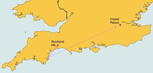
The Crystal Palace transmitter is out of alignment by an angle of 27°. Most TV aerials have an acceptance angle of typically ±20°, but will still pick up some signal at 27° (the first null is typically at 30° to 40°).
After switchover, the problem should improve temporarily whilst the Stockland Hill transmitter power is increased but Crystal Palace remains on low power. However, after switchover is completed in London (2012), the same situation may re-occur:
| Channel | 21 | 22 | 23 | 24 | 25 | 26 | 27 | 28 | 29 | 30 | 31 | 32 | 33 | 34 |
| Stockland Hill | NGW A | D3&4 | SDN | BBC A | NGW B | BBC B | ||||||||
| Power(kW) | 25 | 50 | 25 | 50 | 25 | 50 | ||||||||
| Crystal Palace | SDN | BBC A | NGW A | D3&4 | NGW B | BBC B | ||||||||
| Power(kW) | 200 | 200 | 200 | 200 | 200 | 200 | ||||||||
Adjacent Channel Interference
The Great Parks estate in Paignton provides an interesting example of one of the factors that can affect digital reception - adjacent channel interference (where digital reception is adversely affected by the existing analogue TV signals).
The Digital UK postcode checker indicated that digital reception here is good, as does the Ceefax check.
The following photograph shows the Great Parks estate, at the top of King's Ash Hill, with the Beacon Hill transmitter masts clearly visible behind:
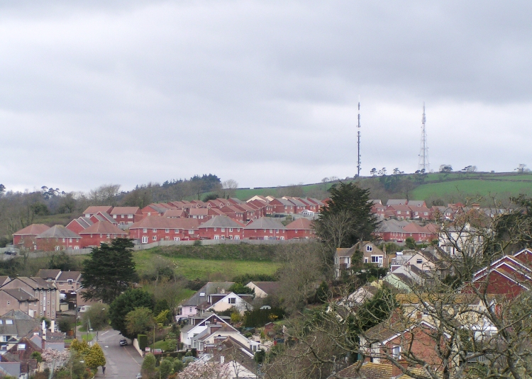
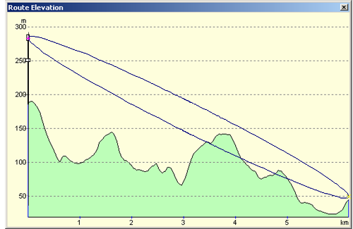
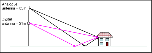
Being so close to the transmitter might suggest that the TV signal would be very good, but digital reception here is actually particularly bad. The terrain between the transmitter and the Great Parks estate looks like this:
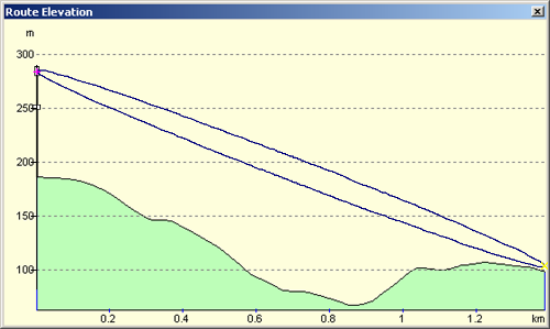
The transmitter mast is located on the left side, with the Great Parks estate on the right. The cross-section shows the valley in between, which carries the stream that continues on into Paignton Zoo. The ellipse drawn onto the cross-section represents the TV signal - in this case the signal is indicated as coming from the analogue antenna at the top of the mast (285m). The ellipse "edge" indicates the zone that needs to be kept clear of any obstructions for ideal reception (the first Fresnel zone). In this example, the path looks ideal.
The next diagram shows the same cross-section for the digital antenna, which is located lower down the Beacon Hill mast (251m):
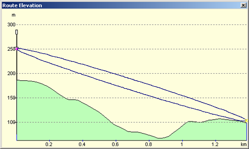
Again, the edge of the ellipse is clear, apart from just touching the ground surface close to the houses on the Great Parks estate. This path also looks ideal.
Measuring signal power on the Great Parks estate gives reasonable powers for most of the channels (target: analogue >60dBµV and digital >45dBµV), so why is the digital reception so poor for some MUXs?
| Channel No. | Analogue (dBµV) | Digital (dBµV) |
| 52 | 37 | |
| 53 | 71 | |
| 54 | 45 | |
| 56 | 37 | |
| 57 | 69 | |
| 58 | 50 | |
| 60 | 78 | |
| 61 | 52 | |
| 63 | 76 | |
| 64 | 51 |
Measuring the carrier to noise (C/N) ratio for the digital channels reveals the problem (though not the underlying reason). For good reception, the recommended carrier to noise ratios need to be at least 22dB (for the QAM16 MUXs) and 26dB for the QAM64 MUXs. At Great Parks, the measured C/N ratio vary widely over the range 8dB to 26dB depending on the exact location, the receiving aerial height and the particular TV channel (MUX) being measured.
| Channel No. | Digital C/N (dB) |
| 52 | 13 |
| 54 | 19 |
| 56 | 22 |
| 58 | 22 |
| 61 | 20 |
| 64 | 17 |
The first noticable effect of interference on digital TV signals is the appearance of missing blocks of picture. A little more interference (or less signal) causes the picture to freeze, and the sound to be affected. Beyond that, the picture disappears and a box appears with a "low signal" message or something similar.
Measuring the threshold sensitivity for a digital receiver by connected to a good aerial / signal produces some interesting numbers. Adding a variable attenuator at the aerial input allows the signal power to be reduced until missing blocks are visible. Measuring the numbers for power and C/N gives the following results:
| Carrier (dBµV) | Carrier to Noise (dB) |
|
| QAM16 | 27 | 10 |
| QAM64 | 33 | 18 |
QAM16 is the modulation format used for the MUXs on CHs 52, 54, 56 & 64 (which include the BBC services). QAM16 is used for four of the MUXs because it is robust - it doesn't carry as much data and doesn't require a high C/N ratio for good reception. QAM16 provides typicallly only 4 or 5 programmes in one MUX).
QAM64 is the modulation format used for the MUXs on CHs 58 and 61. These include ITV and Five. QAM64 can carry 8 or 9 TV programmes, but requires a significantly higher C/N ratio. Reception problems are often noticed first on these MUXs / programmes.
QAM64 will be used exclusively after the switchover. QAM16 is being used prior to the switchover because it works better with the low digital power levels that have to be maintained prior to switchover.
Squeezing the digital MUXs in amongst the existing analogue signals has resulted in a compromise - the digital signals can't be too high in power, or they would interfere with the analogue programmes. The digital signals also have to maintain some power or they would be swamped by the analogue signals. The ideal spectrum would look like this:
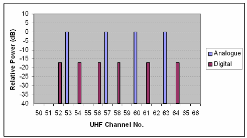
When the digital signals are about 17dB down from the analogue signals, both analogue and digital work quite well together, but when the relative levels change, interference can result
The interference on digital TV at the Great Parks estate comes from the analogue TV signals. This results from using two different antennas on the Beacon Hill mast at different heights (one for digital, the other for analogue).
The digital antenna has a completely different structure to the analogue antenna (see the Local Transmitters page for some photographs). The Great Parks estate is somewhat "underneath" the antenna, and happens to coincide with a "null" in the digital antenna's radiation pattern, but isn't in a null for the analogue antenna. The net result is that although the digital signals seem to have reasonable power, they are actually much smaller than they ought to be when compared with the analogue signals:
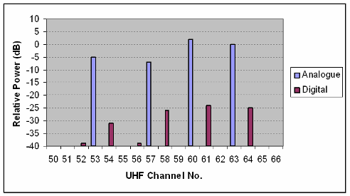
The UHF channels used by the Beacon Hill transmitter position every digital MUX adjacent to an analogue signal. Once the relative amplitude of an analogue signal next to a digital signal is greater than about 22dB, interference with the digital signal will start to become evident, and with analogue signals 30dB higher than the digital MUXs, the digital reception becomes horrible.
Unfortunately, for domestic houses there is no simple solution to this problem - the recommendation from Digital UK is to wait until the analogue service is switched off (so removing the source of interference). Special filters could be installed to improve the situation, but the cost of this is significantly more than other viewing options, hence the proliferation of satellite dishes evident at Great Parks. Single channel filters (which are expensive) could be used for e.g. a block of flats, where the cost can be shared.
Digibox Auto-tuning (to the wrong transmitter!)
When a digibox is set to automatically scan (or re-scan), it starts at the low frequency end (channel 21) and finishes at the high frequency end (channel 68)
This method of scanning a digibox works well provided signals from only one transmitter are present, but when two or more transmitters are available, problems can result.
Many parts of Torbay are able to receive signals from both Stockland Hill and Beacon Hill transmitters. Setting a digibox to scan automatically in such a location will detect the Stockland Hill signals first (since these are low frequency) and populate the programme list accordingly.
When the Beacon Hill signals are detected near the end of the scan (at high frequency), these programmes will also be added to the channel list, typically with numbers in the 800+ range.
The problem is that the "wanted" high frequency channels are not substituted in the digibox's programme list on most digiboxes.
This isn't at all obvious - everyone expects Freeview programme 1 to be BBC1, but may not appreciate that this corresponds to a very poor signal from Stockland Hill rather than the strong signal from Beacon Hill (found on e.g. channel 801).
The same effect occurs on the far side of Kingsbridge (e.g. Hope Cove), where reception from the Redruth transmitter (channels 39 to 50) is low power but good quality (mostly across open sea) and reception from Caradon Hill (channels 21 to 34 plus channel 48) is high power but low quality (due to adjacent channel interference).
Scanning a digibox at Hope Cove detects the channels from Caradon Hill first and populates the programme list with low quality signals. When the Redruth channels are detected these are added to the list with 800+ numbers and hence are difficult to find.
Various methods can be used to avoid this problem:
Tune the digibox manually (not available on all digiboxes)
Filter the signal to remove the unwanted transmitter
Remove the aerial whilst scanning the unwanted channels
If manual tuning is available, then this is the best option - the digibox scans for channels only on the specified channels and ignores all other (unwanted) signals. This requires the user to know the correct channel numbers (or frequencies) for the correct transmitter. Not all digiboxes provide a manual tuning option.
Filters are available for TV applications, but the nature of the changes to the channel numbers pre and post switchover make this a difficult and expensive option.
When no other option is available, the aerial lead can be removed from the digibox whilst it automatically scans across the unwanted channels. Since it has no signal, it will skip these channels and move on looking for a signal. The trick is to reconnect the aerial lead before the scan has moved beyond the wanted channels. This method also requries detailed knowledge of the correct channels on the wanted transmitter, though some digiboxes don't provide a scanning channel number to help identify when to reconnect the aerial lead. In this case, counting the channels (starting from 21) may be required.
At present, with just the main transmitters sending out digital TV signals, getting a digibox to ignore unwanted signals isn't too difficult. However, when the local relays have switched to digital, more signals will then be detected during an auto-scan, and may be correspondingly difficult to avoid.
After switchover, some parts of Torbay will be able to detect digital signals from the main Stockland Hill and Beacon Hill transmitters, as well as the Occombe Valley, Clennon Valley and Torquay Town relays.
The best bet is to ensure that your digibox has the ability to be manually tuned and to become familiar with the manual tuning process. Re-scanning digiboxes will be required at least twice during the switchover process.
Transmitter Antenna Changes
The ratio between the analogue and digital signal powers is critical for digital reception, and the importance of maintaining the signal ratio from the Beacon Hill transmitter itself is clear.
Since last August, the analogue signals have been moved around several different antennas, whilst the digital signals have remained constant. The changes are shown on the Local Transmitters page.
These changes have corresponded with changes in reception for a number of viewers - adjacent channel interference is affected just as much by changes to the analogue signal level as by the digital signal level, hence some viewers will have perceived a degradation in their digital reception when the new antenna at the top of the mast was powered up with the analogue signals. The new antenna appears to be more "efficient" than the old analogue "cylinder" that it replaced.
No further changes are planned for the Beacon Hill analogue signals until the actual switchover date (April 2009).
Terrain: Effect on Reception
Whilst Great Parks has a specific reception problem (see above) caused by a null for the digital antenna, plenty of other locations around the Bay experience variable reception for digital services.
Two terrain effects can contribute:
Obstructions in the "line of sight".
Ground reflections.
The following terrain profile shows the path from Beacon Hill to the centre of Kingskerswell:
The direct line of sight for the top antenna (currently analogue) is just obscurred by the hill (close to the quad bike centre on Moles Lane, near the top of Hamelin Way). This gives some loss for the analogue signals. However, the digital antenna is located lower down the mast, so is effectively "more" obscurred by the hill, resulting in a higher loss. In this example, the difference is about 5.5dB - sufficient to affect the ratio between analogue and digital signals, but not disasterous.
The problem for Torbay is that there are many locations without a clear line of sight to the transmitter, where the same sort of effect can be observed. The problem is worse for a location close to a hill blocking the signal path, since the losses increase as the signal has to diffract more around the obstacle.
The height of the receiving aerial can also make a significant difference to the size of the received signal. Back at the Great Parks estate (see profiles above), the effect of this can be seen by recording the signal power with the aerial mounted on a telescopic mast (allowing the height to be changed). The following chart shows what happens for one channel (in this case BBC2 analogue on CH63).
The chart shows the measurements as black stars, and the calculated signal amplitude from the combination of the direct signal and the reflected signal as the dotted line:
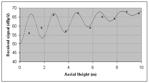
Three different effects can be seen here:
The signal amplitude has an upward trend - a higher aerial will generally give more signal.
The reflections from the field in front of the house produce a significant ripple amplitude of about 10dB.
At very low aerial height, other objects get in the way of the ground reflections and disrupt the ripple pattern
The following sketch (with stretched vertical scale) indicates the direct and reflected paths combining at the receiving aerial / house location.
The height difference between the digital antenna and the analogue antenna on the Beacon Hill also means that the ripple peaks for analogue and digital channels don't overlap, resulting in the signal and carrier to noise variations observed. The different frequencies used for each channel also contributes to some variation in the ripple. Taking all six digital channels and measuring C/N ratio as a function of height gives the following chart:
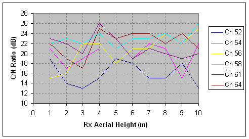
At this location, finding a suitable height for the aerial is rather tricky.
N.B. At 5m height, the C/N ratio for CH54 was so poor that the test meter was unable to make a measurement (it wasn't able to determine that it was a digital signal)!
The effect of ground reflections isn't usually as dramatic as the example above. Reflections are particularly strong when the adjacent ground surface is relatively flat, or tilted upwards towards the transmitter (reducing the angle between the direct path and the reflected path at the receiving aerial).
Margin & The Digital "Cliff Edge"
Analogue TV with poor reception or aerial problems typically results in a "snowy" picture, and interference (e.g. from a power drill) shows up as spots, white lines or "mush". The analogue system can withstand a lot of degradation, giving a gradual reduction in picture "quality" as either the signal reduces, or the interference (electrical "noise") increases.
Digital TV, unlike analogue, does not behave in a graceful manner if things aren't ideal. As the signal strength decreases and / or noise increases, error correction in the digibox keeps the picture looking just the same. This can only work so far - after which point the picture either develops missing chunks or freezes, before both the sound and picture disappear completely. This is know as the "cliff edge" for digital reception - you've either got a picture or you haven't. This property makes it difficult to assess how close to the cliff you are (the "margin"), and can hide deficiencies in a substandard aerial or coax cable.
Some numbers (reducing signal power) may help to clarify this:
|
|
||||||||||||||||||||||||||||||||||||||||
Plotting this on a chart makes the "cliff" more apparent:
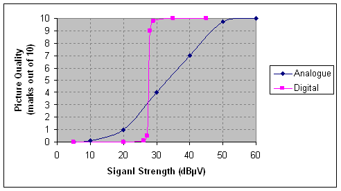
The numbers at the top of the table above are the CAI recommended minimum signal levels; 60dBµV for analogue and 45dBµV for digital. Bear in mind that for digital reception it's really the C/N ratio that matters, rather than absolute signal level. The chart above is for a QAM16 MUX - if a QAM64 MUX was measured the cliff "edge" would move to the right by about 5dB.
A signal reduction of 10dB leaves only 10% of the original signal, a 20dB reduction leaves just 1% and so on. The analogue signal is still "there" with a tiny 0.01% of the recommended minimum signal - it's not a good picture, but you can still make out what's happening and the sound is still good.
The comparison with the digital signal is interesting - the digital picture appears to be "solid" until approaching the digital cliff edge. At this point, a 1dB drop (20% decrease, 80% remaining) in signal has a dramatic affect, and the picture has become unwatchable. A further 1dB drop kills the reception completely. Note also that a signal level that gives nothing for digital reception would give a noisy but watchable analogue picture - this can be a typical signal level for a TV using a set-top aerial.
With a weak digital signal, the picture takes at least half a second or so to reappear when the signal level recovers, as the data for a complete frame isn't transmitted all the time (a requirement of the software compression). Trying to watch a programme with interruptions like this quickly becomes very annoying. With good margin, the digital TV picture will be unaffected by momentary drops in signal, or by electrical noise (from e.g. central heating pump, light switch, kettle etc.).
Terrestrial Analogue and Digital Signal Power
The local relays will maintain the four existing analogue channels until the start of the switchover process.
Switchover begins with BBC2, which will be removed and replaced by ITV's analogue signal. The ITV analogue "space" will be filled by a single digital MUX containing the BBC1, BBC2, BBC Three and BBC News programmes.
The three analogue signals remain and will carry an information banner (advising of the impending analogue switchoff) for one month. During this transition period, switching between analogue and digital receivers will be required to view all the programmes.
After the one month period, the three remaining analogue signals are switched off, and are replaced by two digital MUXs (giving a total of 3 MUXs), providing the rest of the PSB programmes.
See the Channels & MUXs page for more details about the programme content.
Beacon Hill currently transmits digital TV at reduced power to prevent interference with the existing analogue TV signals. After switchover, when the analogue channels are removed, the power for the digital signals will be increased, which will help with margin.
At switchover, all six digital MUXs will be moved onto new channel numbers, with two of the MUXs being moved out of the existing aerial group. In addition, all MUXs will be changed to QAM64 modulation (four are QAM16 currently, with two QAM64). N.B. QAM64 requires about 5dB more signal (& C/N ratio) than QAM16. Digiboxes (but not old OnDigital boxes) can receive both, but require a re-scan (setup menu) to recognise either channel changes or modulation changes. Moving channels out of the existing aerial group reduces their received signal strength by about 3dB (depending on the aerial), so the increase in signal strength of 10dB at switchover will not result in a 10dB increase in margin. Viewers already watching Freeview could find that they have a slightly worse signal for some of the digital programmes. The Channels and MUXs page shows all the details.